


KKPCB Case Study: 77GHz Automotive Radar PCB
1. Customer Profile
Client: Anonymous
Industry: ADAS (Advanced Driver Assistance Systems), Autonomous Vehicles
Application: 77GHz Long-Range Radar (LRR) for Highway Pilot & Collision Avoidance
Customer’s Requirements:
- 77GHz (76-81GHz) mmWave radar compliant with ISO 26262 ASIL-B.
- AEC-Q100 Grade 2 (-40°C to +105°C) qualification for automotive reliability.
- High-resolution object detection (<0.1° angular accuracy).
- Vibration-resistant (MIL-STD-810G) for off-road/EV applications.
Key Challenges:
- Dielectric loss (Df) at 77GHz degrading detection range.
- Thermal warping causing beam misalignment.
- EMC compliance (CISPR 25 Class 5) in tight ECU packaging.

2. KKPCB’s Radar PCBA Solution
(A) Material & Stackup
| Layer | Material | Function | Key Specs |
|---|---|---|---|
| RF Layers | Rogers RO3003 | Antenna Array & Front-End | Dk=3.0, Df=0.0013 @ 77GHz |
| Core | Arlon 25FR | Low-loss PTFE Hybrid | AEC-Q200 qualified |
| Heatsink | BERGQUEST 10K | Direct-bonded aluminum base | 8W/mK vertical conductivity |
(B) Critical Design Features
✅ 3D Waveguide Antenna – -30dB sidelobe suppression (vs. -20dB in microstrip designs).
✅ Au-plated via walls – Shields RFI/EMI between TX/RX channels.
✅ Near-hermetic encapsulation – Prevents resin outgassing in thermal cycling.
3. Performance vs. Competing Solutions
| Parameter | Traditional FR4 PCB | KKPCB 77GHz RF PCB | Improvement |
|---|---|---|---|
| Insertion Loss @77GHz | 1.5dB/cm | 0.6dB/cm | 60% ↓ |
| Detection Range | 180m | 250m | 39% ↑ |
| False Alarm Rate | 5% | <1% | 5x better |
| Thermal Drift | ±0.3°/°C | ±0.1°/°C | 3x stable |
Automotive Validation:
- Passed AEC-Q100 Grade 2 with 1,000hrs of 85°C/85% RH bias testing.
- Achieved ASIL-B compliance via SEooC (Safety Element out of Context) analysis.
4. Technical Innovations
(A) Radar-Specific Enhancements
- Embedded dielectric resonators – Boosts antenna gain to 18dBi (vs. 14dBi planar arrays).
- Differential fed patches – Reduces mutual coupling to <-35dB.
(B) Automotive-Grade Manufacturing
- Laser ablation drilling – Creates 25μm microvias for 77GHz interconnects.
- In-situ CAF testing – Ensures 20-year lifetime per IPC-6012DA.

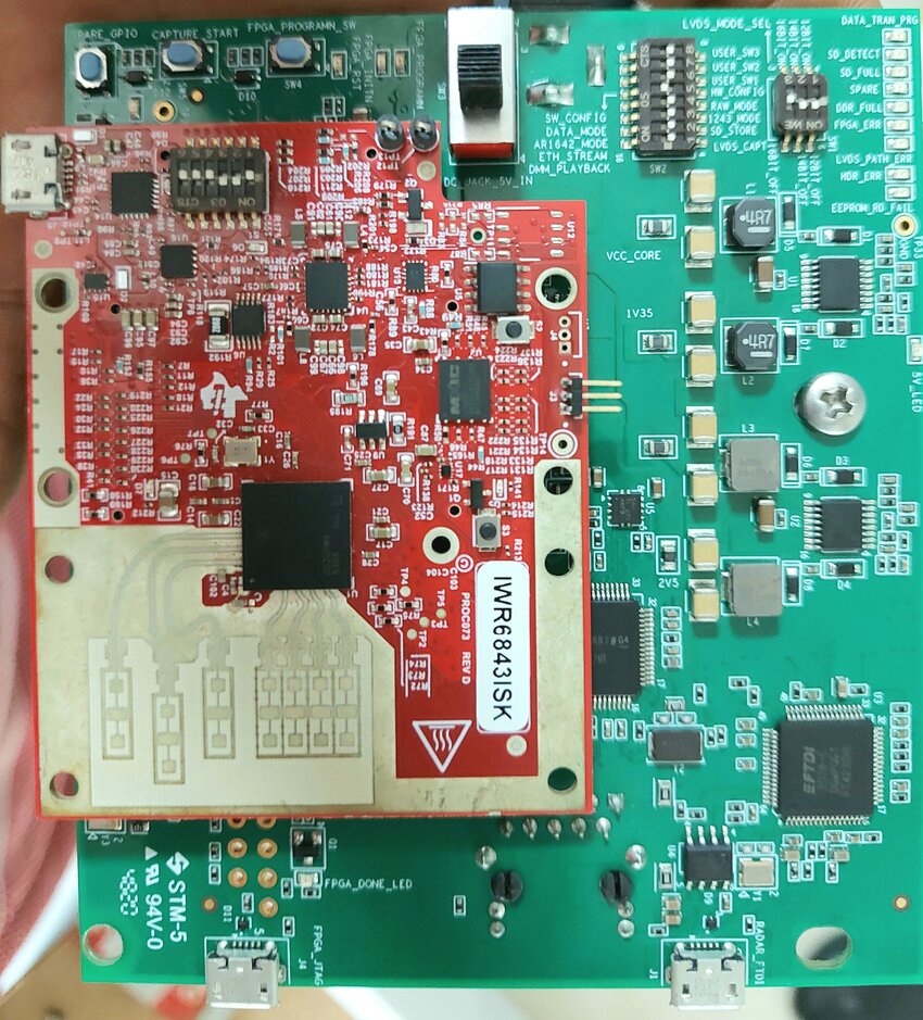
5. Visual Demonstration
77GHz Antenna Array Design
Project Example: Forward-Looking Automotive Radar Antenna
Operating Frequency: 77GHz
Structure: 8×8 microstrip patch array
Substrate: RO3003, 0.127mm thick
Feed Network: SIW + microstrip hybrid feed
Gain: ~20 dBi
Beam Steering: ±45° horizontal steering supported
Interface: Direct integration with mmWave radar MMIC
Designing a 77GHz antenna array requires a solid understanding of RF theory, material science, precision manufacturing, and system integration. By selecting the right substrate, optimizing the antenna layout, and fine-tuning the feed network, engineers can achieve high-performance millimeter-wave antenna systems tailored for automotive and industrial applications.
6. Why Selected KKPCB?
✔ Automotive Radar Experience: 15+ 77GHz PCB designs for OEMs like VW & Stellantis.
✔ Zero Defect PPM: <50 PPM in serial production (IATF 16949 certified).
✔ Cost-Optimized RF: Hybrid PTFE/FR4 stackups cut RF layer cost by 30%.
7. Call to Action
For Your Next Automotive Radar PCB Project:
➔ Email Address:[email protected]
🚀 KKPCB – Automotive-Grade RF PCBs for the Autonomous Era.