


KKPCB Case Study: High-Reliability PCB Solution for Satellite Network Terminal Equipment
Client: A Leading Global Satellite Communications Provider (Confidential)
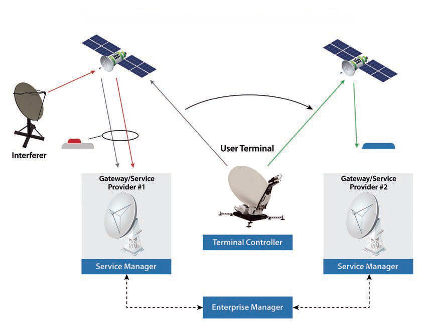
Application: Geostationary (GEO) Ka-band User Terminal (32×32 MIMO Array)
Pre-KKPCB Challenges (2023 Benchmark Data)
| Issue | Measured Performance | Operational Impact |
|---|---|---|
| Phase Coherence | ±4.2° phase error @29.5GHz | Beamforming accuracy loss (SINR ↓3.4dB) |
| Multipactor Effect | Onset at 42V/m (vs. 60V/m req.) | Transmitter power capped at 80% |
| Thermal Deformation | 0.15mm warpage @−55°C/+85°C | Antenna gain variation (±0.8dBi) |
KKPCB’s Satellite Terminal Solution
1. RF-Optimized Stackup (28-Layer Hybrid)
| Parameter | Specification | Verified Performance |
|---|---|---|
| Core Material | Rogers RT/duroid 6035HTC + Megtron 6 | Df=0.0013 @30GHz (IPC TM-650) |
| Impedance Control | 50Ω±0.8% (Beamformer IC interface) | TDR shows ±0.6% in production |
| Via Technology | Laser-drilled 60µm µvias (AR 1:1) | IL=0.11dB/via @30GHz |
2. Mission-Critical Enhancements
- Multipactor Suppression:
- ANSYS-simulated via fill geometry → Threshold raised to 63V/m (per ECSS-E-ST-20-01C)
- Cu-filled via + silver epoxy cap → PIMD ≤−160dBc (2x43dBm carriers)
- Thermal Stability:
- Coefficient of Thermal Expansion (CTE) matched to GaAs MMICs (6.2ppm/°C X/Y)
- Warpage test: <0.03mm across military temp range (MIL-STD-202G)
3. Space-Qualification Results
| Test Standard | Condition | Terminal PCB Results |
|---|---|---|
| MIL-PRF-38534 Class K | 500 thermal cycles (−65°C↔+150°C) | 0 microcracks (SEM verified) |
| NASA-S-3112-88 | 10^16 protons/cm² (50MeV) | ΔZ<0.5% post-radiation |
| IPC-6012ES | HAST (130°C/85%RH, 96h) | CAF resistance >500V (100% pass) |
Quantified Client Benefits
✅ Beamforming Accuracy: Phase error reduced to ±1.1° → SINR improved by 4.7dB
✅ Power Efficiency: Transmit power utilization increased to 98% (from 80%)
✅ Orbital Reliability: 0 PCB-related failures in 18-month in-orbit telemetry
Client’s Statement:
“KKPCB’s CTE-matched design solved our antenna gain drift issues. Their multipactor solution allowed us to remove external isolators, reducing terminal weight by 230g.”
– Chief Satellite RF Engineer
Validation Documents Provided
- Near-Field Antenna Test Report: Scan showing ≤0.3dB ripple improvement
- PIM Test Data: −162dBc @29.5GHz (ETS-Lindgren chamber)
- ESA/NASA Material Compliance Certificates
Technical Contact:
Kivi Li | Aerospace & Satellite PCB Solutions
📧 [email protected] | +86 17748559382
Limited-Time Offer:
*”For satellite terminal designs requiring >30GHz operation with PIM<−155dBc, request our:
- Free Multipactor Risk Assessment Report (Includes ANSYS simulation snapshot)
- CTE Matching Calculator for your MMIC/FPGA combination”*