


A printed circuit board (PCB) consists of an insulating board on which copper layers and signal lines are etched or printed. The number of layers on an industrial PCB can range from one to eight or more as the complexity of the circuit increases.
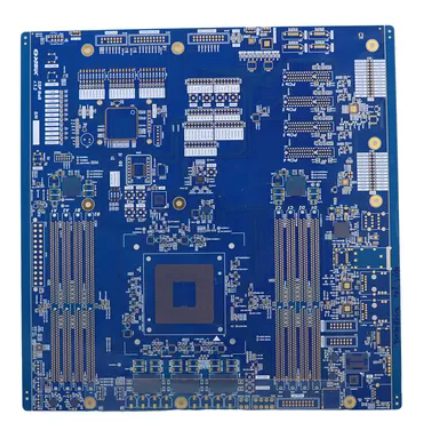
There are many varieties of printed circuit boards in terms of the materials used in their manufacture. Depending on the material, the choice of material determines the properties of any circuit board. Among the various options, high temperature FR4 is one of the high-end materials used in high temperature PCBs.
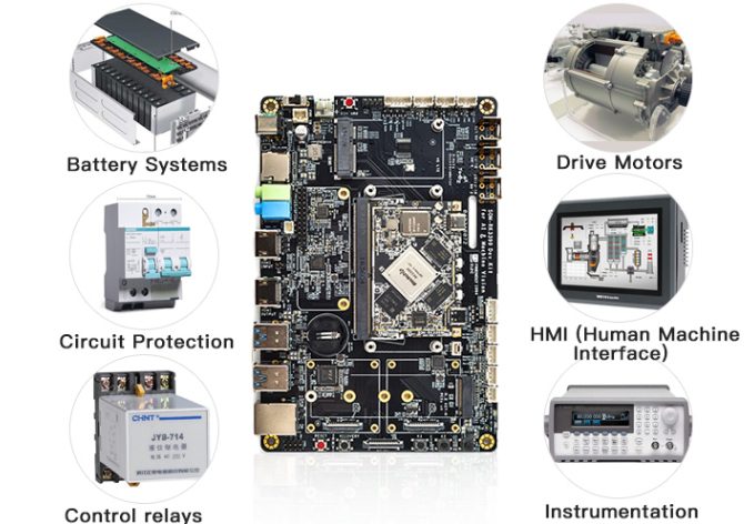
In the era of smart manufacturing, industrial robots are transforming the production landscape with enhanced efficiency, precision, and safety. Central to this evolution is the indispensable role of printed circuit boards (PCBs). Acting as the “nervous system” of robots, PCBs support signal transmission, control functions, and intelligent decision-making. As robotics technology advances, so too does the design and functionality of PCBs.
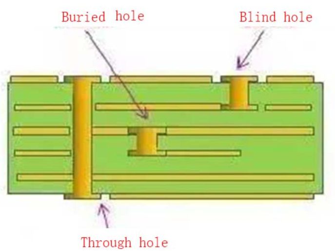
A via is a small hole on a PCB that connects different layers electrically. Structurally, a via consists of a drill hole and a pad.
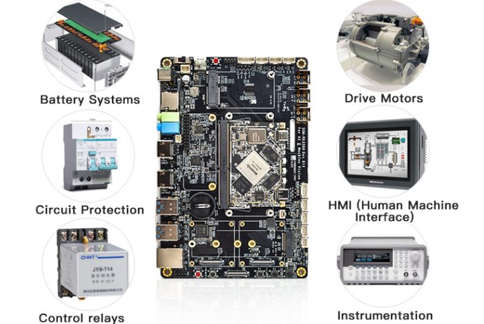
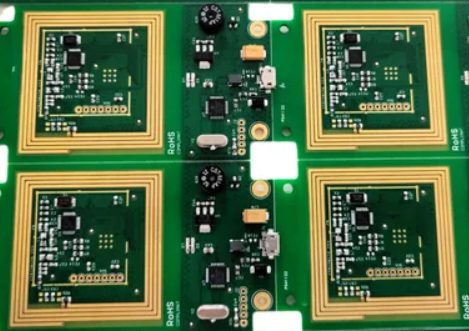
Among our other products, we specialize in providing industrial PCB assemblies that require high reliability and precision. Since electronic devices used in industrial applications need to be very stable and suitable for use in harsh conditions, industrial printed circuit boards also need to follow strict standards to thrive in industrial environments.
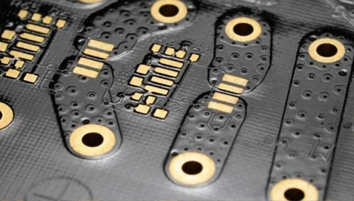
An annular ring refers to the area of copper that surrounds the drilled hole (via) in a PCB. In multi-layer PCBs, vias are essential for connecting various layers. The annular ring ensures strong electrical conductivity between these layers, as it provides the necessary copper coverage around the hole.
The introduction of phenolic resin-based laminates in the 1930s improved mechanical stability and insulation. However, the game-changer was the development of glass-reinforced epoxy laminates (FR-4) in 1940, offering superior electrical insulation, moisture resistance, and mechanical durability.
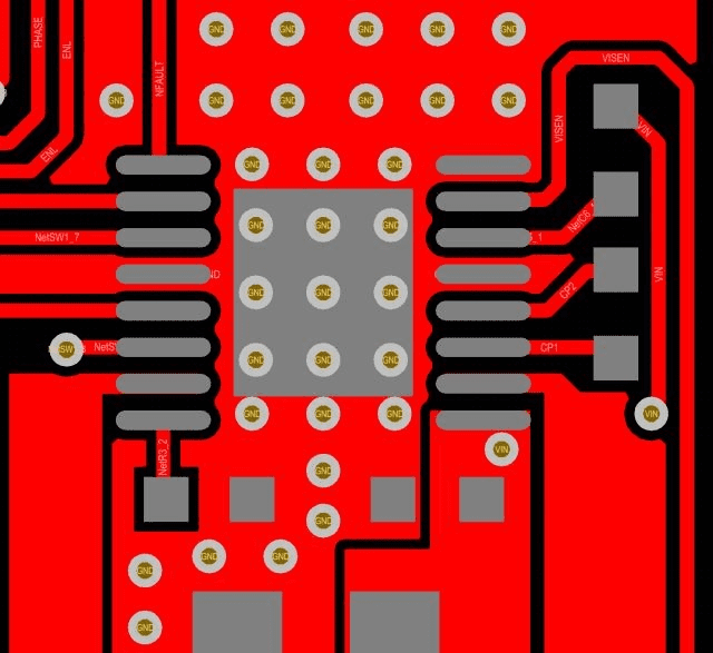
Motor driver ICs handle high currents and dissipate substantial heat, so efficient PCB design is essential to ensure proper heat dissipation and reliable performance. Below are some best practices for designing a robust PCB for motor driver ICs.
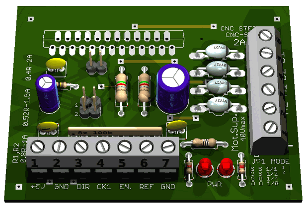
A motor controller is an electronic or electrical device used to regulate the speed, torque, and position of a motor. It can automatically or manually start, stop, and protect the motor from issues like overloads.
Impedance line routing in multi-layer PCBs is both an art and a science. Adhering to the principles of short lines, symmetry, equal length, and precise compensation ensures high-speed data transmission and robust device performance. By leveraging tools like the Polar Si9000 and applying best practices in design, engineers can effectively address challenges in modern PCB impedance routing.