
IT158TC PCB Laminate: Specifications and Design Guide
IT158TC (ITEQ IT-158TC) is a medium-Tg, lead-free-compatible epoxy PCB laminate for designers evaluating multilayer, industrial, automotive, networking and heavy-copper boards. This guide summarizes the manufacturer’s published laminate data and explains the stackup questions to resolve before requesting a fabrication quote. The matching IT-158BS designation refers to prepreg; confirm the exact core and prepreg construction with your fabricator.
IT158TC specifications that matter in PCB design
ITEQ’s IT-158BS/IT-158TC data sheet, revision 01-14, lists a typical glass transition temperature (Tg, DSC) of 155°C, with 150°C as the minimum specification. For laminate at least 0.50 mm thick, the published typical decomposition temperature (Td, 5% weight loss) is 345°C, with a 325°C minimum. These values describe standardized material tests, not an allowable continuous operating temperature or a guarantee for a finished assembly.
At 50% resin content, the data sheet reports typical dielectric constant (Dk) values of 4.3 at 1 GHz and 4.0 at 10 GHz for laminate at least 0.50 mm thick. Typical loss tangent (Df) is 0.016 at 1 GHz and 0.018 at 10 GHz for that thickness range. Dk and Df depend on frequency, resin content, glass style and test method. Use the chosen construction’s controlled-impedance data for line-width calculations rather than treating one catalog value as universal.
The published typical Z-axis expansion from 50°C to 260°C is 3.3% for laminate at least 0.50 mm thick. The same table gives a typical T260 greater than 60 minutes and T288 greater than 30 minutes. ITEQ describes the material as suitable for lead-free assembly with a maximum reflow temperature of 260°C and highlights CAF resistance. These are material-selection inputs; validate the actual board and assembly profile against the approved stackup and process.
When should you choose IT158TC?
IT158TC laminate is worth considering when a conventional multilayer design needs medium Tg, lead-free processing compatibility and attention to thermal cycling or conductive anodic filament risk. ITEQ lists multilayer PCB, industrial, automobile, server and networking, telecommunications, and heavy-copper applications. That application list is a starting point, not a qualification for every end product.
For high-speed signals, determine whether the dielectric loss budget at the actual frequency and trace length is acceptable. A published Df of roughly 0.016 to 0.018 across 1–10 GHz does not make IT158TC interchangeable with a purpose-built low-loss RF laminate. Compare insertion-loss targets and glass-weave effects with alternatives before freezing the design. See KKPCB’s high-frequency PCB and PCB materials pages for related selection considerations.
Stackup and fabrication checklist
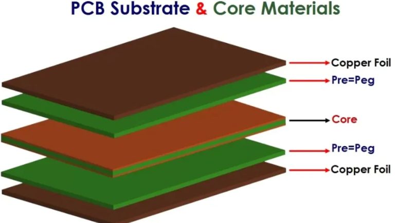
- Confirm construction: specify IT158TC laminate, IT-158BS prepreg, finished thickness, layer count, glass style, resin content and copper weight. Do not assume every thickness has identical properties.
- Define impedance: provide target impedance, tolerance, reference planes, trace geometry and operating frequency. Ask for a stackup based on the available core and prepreg builds.
- Review holes and heat: share finished drill sizes, aspect ratio, via density, thermal cycling requirements and maximum assembly reflow conditions. Material Tg alone cannot predict plated-through-hole life.
- Specify verification: identify IPC class, test coupons, impedance measurement, microsection and any CAF or reliability testing your product requires.
In multilayer PCB manufacturing, material choice interacts with copper balance, lamination, drilling and plating. If a board uses thick copper or repeated assembly heat, request a process review before committing to volume production. Stackup approval should include the material revision and any permitted substitutions.
IT158TC FAQ
Is IT158TC the same as IT-158BS?
No. ITEQ’s combined data sheet names IT-158TC as laminate and IT-158BS as prepreg. A multilayer stackup may use both, subject to the selected build.
Does Tg 155°C mean the PCB can operate continuously at 155°C?
No. Tg is a transition measured by a defined test. Continuous-use limits depend on the material’s approvals, board construction, components and operating environment.
Can IT158TC be used for controlled impedance?
Yes, if the complete dielectric construction and manufacturing tolerances support the target. Ask for construction-specific Dk and a confirmed impedance stackup; do not copy line widths from an unrelated material.
Request a material and stackup review
Send your Gerber or ODB++ files, layer order, finished thickness, copper weights, impedance table, quantity and assembly thermal profile through KKPCB’s RFQ contact page. Request confirmation of IT158TC availability, exact laminate and prepreg construction, and any proposed substitution before an order is approved.
Technical source: ITEQ IT-158BS/IT-158TC manufacturer data sheet (Rev. 01-14). Typical values are reference data; verify the current manufacturer revision and purchase specification for your project.
