

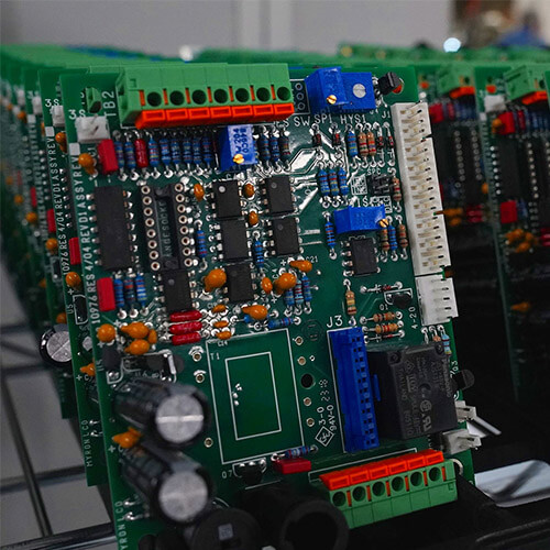


Flexible PCB Materials: 7 Key Choices for Reliable FPCs
Flexible PCB materials determine whether an FPC survives bending, heat, vibration, chemical exposure, and repeated assembly. A reliable flex circuit is not simply a thin rigid PCB: its substrate, copper, adhesive, coverlay, stiffener, and surface finish must work as one mechanical system. This guide explains the seven material choices engineers should review before releasing a flexible PCB design for quotation or production.
1. Understand the complete flexible PCB material stack
A typical flex circuit contains a dielectric film, copper foil, bonding adhesive or an adhesiveless copper-to-film interface, coverlay, and optional stiffeners. Plated holes, surface finish, legends, and pressure-sensitive adhesive may also be required. Every layer changes thickness, flexibility, thermal performance, and reliability. For this reason, flexible PCB materials should be selected from the finished stackup rather than as isolated items.
| Material element | Common options | Main design impact |
|---|---|---|
| Base film | Polyimide, polyester, LCP | Temperature range, moisture absorption, dielectric behavior, flexibility |
| Copper foil | Rolled-annealed or electrodeposited | Dynamic bend life, conductor strength, cost |
| Bonding system | Adhesive-based or adhesiveless | Total thickness, dimensional stability, via reliability |
| Cover layer | Polyimide coverlay or flexible solder mask | Conductor protection, bend performance, fine-feature capability |
| Stiffener | Polyimide, FR-4, stainless steel | Connector support, local rigidity, assembly handling |

2. Polyimide and other substrate films
Polyimide film is the standard dielectric for most flexible circuits because it combines a wide service-temperature range, good mechanical strength, chemical resistance, and stable electrical properties. It is suitable for soldering processes and for static or dynamic bending when the finished stack is designed correctly. Polyimide is not a thermosetting resin that simply remains rigid after heating; it is selected because the thin film remains flexible while tolerating manufacturing and operating temperatures.
Polyester can be economical for simple, lower-temperature circuits such as membrane switches, but its thermal limits make it less suitable for conventional reflow assembly. Liquid crystal polymer, or LCP, offers low moisture absorption and attractive high-frequency performance, although material availability and processing cost must be reviewed. Engineers should define temperature, humidity, bend life, frequency, and chemical exposure before selecting the dielectric. KKPCB’s PCB materials overview provides additional laminate categories for comparison.
3. Choose copper foil for the required bend life
Rolled-annealed (RA) copper has an elongated grain structure and is generally preferred for dynamic flexing and tight bend areas. Electrodeposited (ED) copper is widely used in static flex and rigid PCB applications and can be cost-effective when repeated movement is not expected. Modern high-ductility ED grades may be appropriate for some flex designs, but the exact foil grade and qualification data should be confirmed rather than relying only on the RA or ED label.
Copper thickness also matters. Thicker copper increases current capacity but raises bending strain and may require a larger bend radius. Thin copper improves flexibility but reduces conductor cross-section and can increase fabrication sensitivity. The neutral bend axis, copper grain direction, conductor width, and total stack thickness should be evaluated together. Route traces perpendicular to the bend line, avoid abrupt width changes, and keep plated holes, component pads, and copper discontinuities out of the active bend zone.
4. Adhesive-based vs adhesiveless flex laminates
Adhesive-based laminates bond copper to polyimide with acrylic or epoxy adhesive. They are mature and economical, but the adhesive adds thickness and can increase dimensional movement, moisture uptake, and stress around plated through-holes. Adhesiveless laminates bond copper directly to the dielectric or use a very thin tie layer. They enable thinner constructions, tighter bending, finer features, and improved thermal and dimensional performance.
Adhesiveless material is often preferred for multilayer flex, fine-pitch circuitry, controlled impedance, and reliability-critical designs. Adhesive-based constructions still perform well when their thickness and thermal behavior fit the application. The decision must reflect qualification requirements and total installed cost, not the laminate price alone. A rigid-flex circuit can carry signals continuously between rigid and flex regions; the original article’s suggestion that signals cannot cross the transition was incorrect. Review the transition design and stackup through KKPCB’s rigid-flex PCB manufacturing page.
5. Coverlay, surface finish, and stiffeners
Polyimide coverlay protects copper while retaining flexibility. Its adhesive flows during lamination, so the fabricator needs realistic openings and allowances for adhesive squeeze-out. Flexible photoimageable solder mask can support smaller openings and dense features, but it is usually less tolerant of repeated bending than coverlay. Some designs use both: coverlay in bending areas and flexible solder mask near dense pads.
Connector fingers and exposed pads commonly use ENIG, immersion tin, OSP, or hard gold, depending on solderability, contact wear, flatness, and storage requirements. FR-4 stiffeners support ZIF connectors and component areas; polyimide stiffeners reinforce thin regions with less thickness; stainless steel can provide very high local rigidity. Stiffener edges should not terminate at a critical bend, because a sudden stiffness change concentrates strain.
6. Match flexible PCB materials to the application
Static flex, flex-to-install, and dynamic flex are different reliability cases. A static flex circuit is bent only during installation, while a dynamic circuit may move millions of times. Dynamic applications require careful control of copper type, grain direction, layer count, conductor placement, bend radius, and coverlay transitions. As conservative starting points, many teams use larger bend radii as layer count and flexing frequency increase, but the final rule must come from the selected material system, IPC-2223 guidance, and the fabricator’s verified capability.
- Medical and wearable devices: prioritize thin stacks, repeated-flex reliability, biocompatibility requirements, and cleaning-chemical exposure.
- Automotive and industrial electronics: review temperature cycling, vibration, oils, moisture, and connector retention.
- RF and high-speed designs: control dielectric thickness, copper roughness, impedance, insertion loss, and reference-plane continuity.
- Battery and power circuits: balance current capacity, copper thickness, thermal rise, and bend strain.
For formal design requirements, consult the applicable edition of IPC-2223, Sectional Design Standard for Flexible/Rigid-Flexible Printed Boards, together with customer and industry-specific standards.
7. Flexible PCB material DFM checklist
Before requesting a quotation, provide enough information for the manufacturer to validate the complete flexible PCB materials system. A Gerber or ODB++ package without mechanical and operating requirements is not enough for a dynamic or reliability-critical design.
- Define static, flex-to-install, or dynamic use and the required cycle life.
- State the minimum inside bend radius, bend direction, and installation envelope.
- Specify substrate, copper type and thickness, adhesive preference, coverlay, and stiffeners.
- Identify controlled-impedance traces and whether they pass through a bend or rigid-flex transition.
- Provide operating temperature, chemical exposure, current, voltage, and regulatory requirements.
- Confirm connector-contact finish, stiffener thickness, tolerance, and insertion direction.
- Request stackup, impedance, microsection, electrical test, and dynamic bend-test requirements as applicable.
A complete flexible PCB materials review prevents avoidable failures at bends, connector transitions, plated holes, and component areas. It also ensures the selected flexible PCB materials match the required temperature, movement, electrical performance, and assembly process.
Request a flexible PCB material and DFM review
KKPCB manufactures prototypes and production flexible PCB circuit boards, including single-sided, double-sided, multilayer, and rigid-flex constructions. Send the stackup, Gerber or ODB++ files, drawings, BOM, bend requirements, and expected volume through the KKPCB RFQ contact page. Our engineering team can review flexible PCB materials, bend zones, coverlay, stiffeners, impedance, panelization, and assembly risk before production.
